

Hydraulic Guide pump · valve · actuators
Excavator Main Hydraulic System
Components, Oil Flow & Operator Checks
Reservoir → pump → valve → actuator → return
A practical operator guide to the excavator hydraulic system: how oil moves, what the major components do, why pressure and flow matter, and what to check before, during and after work.
Read the machine as one hydraulic loop.
How does an excavator hydraulic system work?
An excavator converts engine power into controlled hydraulic movement. The engine drives the hydraulic pump group; the pumps supply oil flow; the main control valve meters that flow to a cylinder or hydraulic motor; the actuator produces movement; and the returning oil travels back through the return circuit toward the reservoir. Volvo Construction Equipment describes this same basic sequence of engine-powered pumps, valves, cylinders and motors. [1]
The practical path to remember is reservoir → pump → main control valve → cylinder or motor → return circuit → reservoir. Once an operator understands that path, boom, stick, bucket, swing and travel behaviour become easier to read from the seat.
Follow the oil
The excavator hydraulic power path
Hydraulic excavators use pressurised oil to transmit power from the engine-driven pump group to the machine’s working actuators. Volvo’s current excavator hydraulics guide describes the same core sequence: pump action, directional control through valves and hoses, and cylinders or motors converting fluid energy into movement. [1]
Reservoir supplies oil
The hydraulic tank stores the oil used throughout the circuit and provides the pump supply.
Engine drives the pumps
Mechanical engine power turns the main pump group.
Pumps supply flow
Variable-displacement piston pumps are common on hydraulic excavators. John Deere lists variable-displacement axial-piston main pumps on its 75G and 85G excavators. [2]
Main valve directs oil
The selected valve section meters pump flow toward boom, stick, bucket, swing, travel or auxiliary functions.
Actuator performs work
A cylinder extends or retracts, or a hydraulic motor rotates.
Return oil leaves the actuator
Oil displaced from the opposite side travels through the return side of the circuit.
Oil is cooled and filtered
The return circuit manages heat and contamination before the oil is reused.
Engine supplies mechanical power → pump supplies hydraulic flow → valve sends it → actuator moves → oil returns.
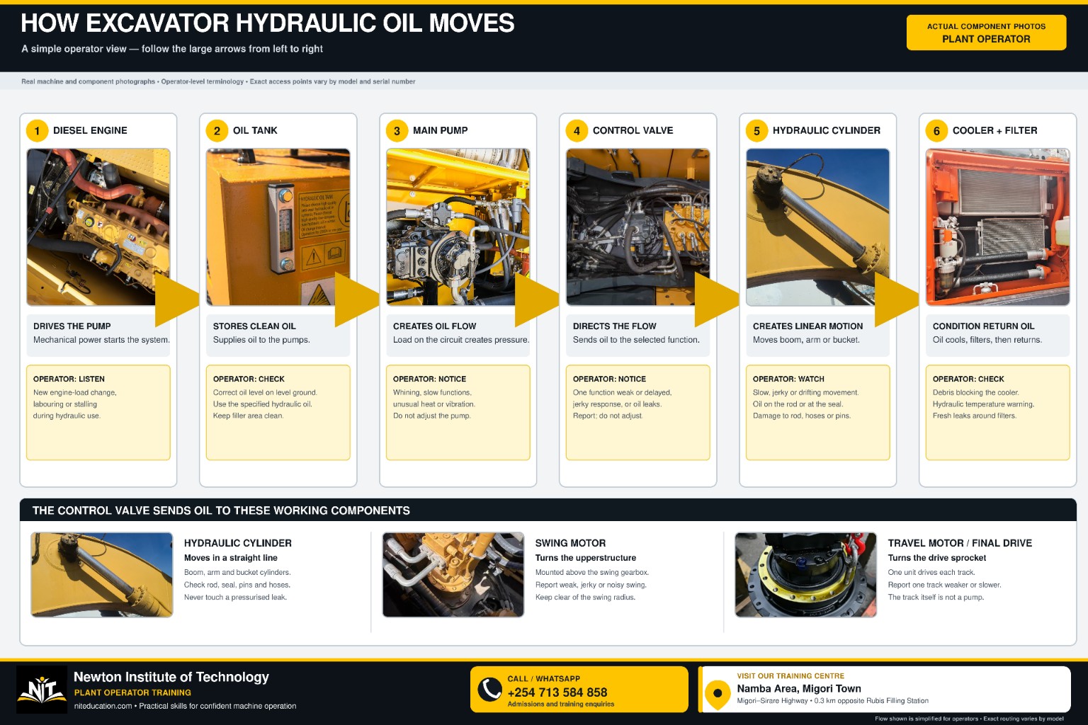
Component map
Main excavator hydraulic-system components and what they do
| Component | Main function | What the operator should understand |
|---|---|---|
| Hydraulic reservoir | Stores hydraulic oil and supplies the pump circuit. | Oil level, tank condition, visible leakage and cleanliness matter. |
| Diesel engine | Supplies mechanical power to the hydraulic pump group. | Hydraulic performance depends on available engine power. |
| Main hydraulic pump(s) | Supply hydraulic flow to the machine circuits. | Many excavators use variable-displacement axial-piston pumps that adjust output with demand. [2] [3] |
| Main control valve | Meters and directs oil to the selected function. | Different machine functions share a central hydraulic control system. |
| Boom cylinder(s) | Raise and lower the boom. | Watch speed, smoothness, rod condition, seals, hoses and holding behaviour. |
| Stick / arm cylinder | Moves the stick in and out. | Stick movement is normally blended with boom and bucket movement during digging. |
| Bucket cylinder | Produces bucket curl and dump movement through the linkage. | Observe rod, seal, hose and linkage-area condition. |
| Swing motor + reduction | Rotates the upper structure. | Hydraulic energy becomes rotary motion and is reduced through gearing. |
| Travel motors | Provide hydraulic rotary power for left and right travel. | Compare both sides when judging travel response. |
| Final drives | Reduce speed and multiply usable drive torque at the sprockets. | Travel power passes from hydraulic motor through gearing to each track. |
| Centre swivel | Carries hydraulic services between the rotating upper structure and lower travel circuits. | Leakage around the centre area can be an important observation. |
| Hydraulic cooler | Removes heat from hydraulic oil. | Blocked airflow and leaking cooler lines can affect system temperature. |
| Hydraulic filters | Remove contamination from circulating oil. | Clean oil protects closely fitted hydraulic components. |
| Hoses and rigid pipes | Carry hydraulic oil between components. | Routing, abrasion, cracks, bulges, fittings and leakage need regular inspection. [5] |

Supply side
Reservoir, engine and main hydraulic pumps
Hydraulic reservoir
The reservoir stores the system oil and feeds the pump circuit. Returning oil eventually comes back to the tank after doing work. From an operator’s perspective, the practical inspection points are oil level, visible leakage, tank condition, filler/breather condition and major connections.
Engine + pump group
The engine turns the hydraulic pump group. Parker’s hydraulic-pump training distinguishes fixed-displacement pumps from variable-displacement pumps, where flow can be varied at a given shaft speed. [3] Excavators commonly use variable-displacement piston pumps so hydraulic output can respond to machine demand.
Some excavators use two main pumps mounted together; others use a different pump count or architecture. The operator does not need to memorise every manufacturer’s internal design. The useful principle is that the pump group supplies the flow used by the work equipment, swing and travel circuits.
Two different hydraulic ideas
Hydraulic flow versus hydraulic pressure
Flow
Flow is the quantity of hydraulic oil moving through the circuit over time. More available flow generally allows a cylinder to move faster or a hydraulic motor to rotate faster. Volvo explains flow as the hydraulic quantity that strongly affects excavator movement speed. [1]
Pressure
Pressure develops as flow meets resistance from the load. That pressure produces cylinder force or motor torque within the machine’s designed limits. Volvo describes pressure as the hydraulic “muscle” used to overcome working resistance. [1]
Distribution centre
What the main control valve does
Pump flow enters the main control valve. Individual valve sections then meter and route oil to the function requested by the operator. Depending on the excavator, the command may be transmitted by hydraulic pilot controls, electronic-over-hydraulic controls or another manufacturer-specific arrangement. Volvo describes the main control valve as the component that regulates and directs hydraulic flow to actuators. [1]
Boom circuit
Directs controlled oil to the boom cylinder or cylinders for raising and lowering.
Stick circuit
Controls stick-in and stick-out movement through the arm cylinder.
Bucket circuit
Controls curl and dump through the bucket cylinder and linkage.
Swing circuit
Sends flow to the swing motor to rotate the upper structure.
Left travel
Controls hydraulic power sent toward the left travel motor.
Right travel
Controls hydraulic power sent toward the right travel motor.
Where hydraulic power becomes movement
Cylinders, swing motor and travel motors
Double-acting cylinders
Boom, stick and bucket cylinders are normally double-acting. Oil can be directed to either side of the piston. Pressure on one side moves the piston while oil from the opposite side returns; reversing the valve connections reverses the cylinder movement.
Hydraulic motors
Swing and travel use hydraulic rotary motion. The swing motor rotates the upper structure through reduction gearing. Travel motors send rotary power through final drives to the sprockets and tracks. John Deere identifies axial-piston travel motors in its excavator specifications. [2]
Cylinder = straight-line movement. Hydraulic motor = rotary movement.
Why this knowledge matters
30 practical reasons a plant operator should understand excavator hydraulics
An operator does not need workshop-level hydraulic theory to benefit from hydraulic knowledge. The goal is to connect controls with machine response, recognise change early and report it precisely. NIT’s wider Excavator Parts and Functions guide follows the same operator approach: know the part, know its function and know what change is worth reporting. [7]
Operate with understanding
- Connect joystick movement with what happens inside the hydraulic system.
- Know which actuator moves the boom, stick, bucket, swing and tracks.
- Blend boom, stick and bucket functions more smoothly.
- Understand why simultaneous functions share hydraulic demand.
- Recognise the machine’s normal hydraulic response.
Notice performance changes
- Spot a new reduction in actuator speed.
- Notice a loss of digging or lifting force.
- Separate a single-function change from a whole-system change.
- Recognise new hydraulic noise or vibration.
- Recognise jerky, delayed or inconsistent movement.
Inspect more effectively
- Pay attention to unusual hydraulic temperature behaviour.
- Carry out a more purposeful hydraulic pre-start check.
- Inspect hoses for abrasion, cracks, bulges, twisting and leakage. [5]
- Notice developing cylinder-seal leakage.
- Identify scoring, pitting or other visible cylinder-rod damage.
Protect the system
- Understand why unexpected cylinder drift deserves attention.
- Understand why the correct hydraulic-oil level matters.
- Value contamination control around hydraulic components.
- Keep couplers and disconnected hydraulic connections clean.
- Distinguish speed-related symptoms from load-response symptoms.
Read swing and travel behaviour
- Understand how hydraulic power produces swing.
- Understand how travel motors and final drives move the tracks.
- Compare left and right travel response.
- Compare cold-machine and fully warmed hydraulic behaviour.
- Notice problems that appear only when the machine is working against resistance.
Report and protect the machine
- Give maintenance personnel precise operating symptoms.
- Recognise developing problems earlier.
- Protect high-value pumps, valves, cylinders and motors through better operating habits.
- Reduce avoidable downtime through early reporting.
- Become an operator who understands the machine, not only the controls.
Hydraulics in real work
What the hydraulic system is doing during a digging cycle
Position the bucket
Use boom, stick and bucket movement to place the cutting edge at the intended entry point.
Enter the material
Hydraulic pressure rises as the bucket meets resistance.
Fill the bucket
Stick-in and bucket curl are blended while boom movement controls depth and path.
Lift
Boom cylinders raise the loaded attachment while other functions can be trimmed at the same time.
Swing
Pump flow is directed toward the swing motor to rotate the upper structure.
Dump and return
The bucket dumps, swing reverses and the work equipment returns for the next cycle.
Modern excavator systems can manage simultaneous hydraulic demand using flow combination, priority functions and regeneration. Volvo documents pump-flow summation, priority functions and regeneration in its current excavator hydraulics explanation. [1]

Before starting work
Hydraulic-only morning check: follow the oil circuit
This hydraulic check is one part of the excavator’s complete pre-start inspection. For the whole-machine routine—work area, undercarriage, attachments, engine, cab and functional checks—use NIT’s dedicated Plant Operator Pre-Start Inspection Checklist. [8]
For the hydraulic system, use one repeatable route: ground → reservoir → pump → main control valve → hoses → cylinders → swing → centre swivel → travel → cooler/filter.
| Inspection point | What to check before work |
|---|---|
| Ground beneath machine | Fresh hydraulic oil, drips or a new wet patch. |
| Hydraulic reservoir | Oil level using the specified checking condition; tank condition and visible leakage. |
| Filler / breather area | Secure condition and cleanliness around the service point. |
| Main pump area | Fresh oil, wet fittings, damaged hoses, loose hardware or unusual oily buildup. Caterpillar includes pump-area leaks and damage in routine hydraulic inspection. [4] |
| Main hydraulic hoses | Abrasion, cracking, bulges, twisting, leaks, damaged outer cover or exposed reinforcement. [5] |
| Hose routing | Rubbing, sharp contact, poor bend position or movement out of normal routing. |
| Clamps and supports | Loose, missing or damaged support that can let a hose rub or move excessively. [4] |
| Main control valve area | Visible leakage, wet fittings or damaged accessible lines. |
| Boom cylinder(s) | Rod surface, gland/seal area, hoses, fittings and visible leakage. |
| Stick cylinder | Rod, seals, hose condition and fresh oil around connections. |
| Bucket cylinder | Rod, seals, hoses and the moving hose route near the bucket linkage. |
| Boom and stick hose runs | Flex points, sleeves, guides, clamps and rubbing near joints. |
| Auxiliary hydraulics | Hoses, couplers and connections where an attachment circuit is fitted. |
| Swing hydraulic area | Accessible hoses, fittings and visible leakage. |
| Centre swivel area | Visible hydraulic oil around the rotating centre joint. |
| Left travel circuit | Travel-motor area, lines and visible leakage. |
| Right travel circuit | Same inspection, comparing condition with the left side. |
| Hydraulic cooler | Heavy debris, blocked airflow, visible damage or leakage. |
| Cooler hoses | Wet connections, abrasion or hose deterioration. Caterpillar specifically includes cooler lines in hydraulic inspection. [4] |
| Filter / return area | Visible leakage, damaged lines or abnormal condition around housings and connections. |
Caterpillar recommends daily pre-shift inspection of hydraulic hose assemblies and identifies abrasion, bubbles, cracking, twisting and leaks among the conditions worth finding early. [5]
After the engine starts
Hydraulic function check before heavy work
Listen for new hydraulic noise, watch the machine monitor and observe whether any movement is unusually slow, jerky, weak or delayed. Caterpillar recommends combining visual inspection with listening for unusual noises, excess heat, vibration or slower implement performance. [5]
From the operator’s seat
What to monitor while the excavator is working
Speed
Has boom, stick, bucket, swing or travel become noticeably slower?
Force
Does a function move freely without load but lose useful force against resistance?
Smoothness
Has movement become jerky, hesitant or inconsistent?
Sound
Is there a new whine, grinding sound, knock or vibration?
Temperature
Is hydraulic temperature behaving differently from the machine’s normal working pattern?
Left vs right
Does one travel side or one swing direction behave differently from the other?
What changed compared with normal operation? Record when the change appears: cold or hot, loaded or unloaded, one function or several.
After work
End-of-shift hydraulic-system checks
The end-of-shift inspection answers a different question from the morning check: what changed while the system was hot and working? Caterpillar’s hydraulic inspection procedure uses a dry, level surface, lowered implements, hydraulic lockout and engine shutdown before close inspection, followed by checks of gauges, pump area, hoses, clamps, cooler lines, cylinders and seals. [4]
| End-of-shift point | What to look for or record |
|---|---|
| Final operating behaviour | Any function that became slower, weaker, hotter, noisier or less smooth. |
| Ground below machine | Fresh hydraulic oil that was not present at the beginning of the shift. |
| Reservoir | Oil-level condition and new evidence of leakage. |
| Main pump area | Hot-condition seepage, fresh oil, wet fittings or damaged lines. |
| Main control valve | Fresh oil around accessible valve sections, lines or fittings. |
| Hydraulic hoses | New rubbing, abrasion, cracking, bulging, twisting or leakage. [5] |
| Hose supports | Movement or damage caused during operation. |
| Boom cylinder(s) | Rod condition, seal leakage and hose/fitting condition. |
| Stick cylinder | Fresh oil, scoring or abnormal dirt buildup around seals. |
| Bucket cylinder | Leakage and hose condition around the working end. |
| Swing area | Visible leakage plus any change noticed during swing. |
| Centre swivel | New leakage around the rotating centre area. |
| Left travel system | Leakage and any change in travel behaviour. |
| Right travel system | Compare directly with the left side. |
| Hydraulic cooler | Debris, restricted airflow, damaged connections or leakage. |
| Filter / return area | Fresh leakage or visible damage. |
| Auxiliary hydraulics | Hoses, couplers and fittings used during the shift. |
| Monitor / display | Hydraulic warnings, abnormal temperature or other new machine messages. |
| Defect report | Exact function, condition, time and visible evidence. |
Clear defect reporting
How to describe a hydraulic change clearly
Operator-level hydraulic knowledge is most valuable when it produces a precise report. Record what changed → which function → which direction → cold or hot → loaded or unloaded → continuous or intermittent.
| What you notice | Useful operator report |
|---|---|
| All functions slow | “Boom, stick, bucket and swing are all slower after the machine reaches normal working temperature.” |
| One function slow | “Stick-in is slow; stick-out, boom and bucket remain normal.” |
| Weak under load | “Bucket movement is normal in free air but loses useful force in compacted material.” |
| Jerky movement | “Boom-up starts smoothly, then jerks through the middle of the stroke.” |
| Temperature change | “Hydraulic temperature rises during continuous loading cycles.” |
| Pump-area noise | “A new whining sound appears when boom-up and stick-in are combined.” |
| Cylinder drift | “The boom lowers gradually when the control is in neutral.” |
| Swing change | “Left swing is normal; right swing becomes slower when the machine is warm.” |
| One weak track | “Right travel becomes weaker than left after about two hours of work.” |
| Visible oil | “Fresh hydraulic oil is appearing around the bucket-cylinder hose fitting.” |
That information gives maintenance personnel a much stronger starting point than a general statement such as “the hydraulics are weak.”
One essential hydraulic rule
Never search for a pressurised hydraulic leak with your hand
A pinhole hydraulic leak can release fluid at enough pressure to penetrate skin. OSHA documents hospitalisation after hydraulic fluid was injected through a pinhole in a high-pressure hose. [6]
Position the machine safely, control stored hydraulic pressure as specified for the machine and use the approved leak-inspection method. Caterpillar also directs users to release hydraulic pressure and allow components to cool before close inspection. [4]
Newton Institute of Technology
How we teach the excavator hydraulic system practically
The useful way to learn hydraulics is to connect the diagram with the machine. At Newton Institute of Technology, the trainee can identify the major components, trace the working path, operate the function, recognise normal behaviour and then use the same knowledge during inspection and defect reporting. NIT’s excavator training resources place hydraulic-system knowledge alongside controls, pre-operation inspection and coordinated machine movement. [9]
inspect it → report what changedMachine-side demonstration
12-step NIT hydraulic-system practical lesson
Locate the reservoir
Identify the tank, oil-level checking point and major visible hydraulic connections.
Locate the pump group
Trace mechanical power from the engine toward the main hydraulic pumps.
Follow the main lines
Trace the major hydraulic lines leaving the pump area toward the control system.
Identify the main control valve
Connect the valve assembly with boom, stick, bucket, swing and travel circuits.
Trace the boom circuit
Follow pump → valve → boom cylinder → movement → return path.
Observe the stick cylinder
Watch rod movement during stick-in and stick-out.
Observe bucket linkage
Connect cylinder movement with bucket curl and dump.
Compare cylinder and motor
See the difference between linear cylinder movement and rotary swing movement.
Trace travel power
Follow hydraulic power to travel motor → final drive → sprocket → track.
Operate one function at a time
Establish clean control response before combining movements.
Blend functions
Combine boom, stick, bucket and swing progressively and feel how hydraulic demand changes.
Inspect and report
Complete the morning check, monitor the system during work and finish with an end-of-shift defect report.
One routine to remember
Before · during · after
Use the same hydraulic thinking every shift.
- Before work: LOOK → CHECK → TRACE → START → TEST.
- During work: LISTEN → FEEL → WATCH → COMPARE.
- After work: PARK → LOWER → SHUT DOWN → INSPECT → CLEAN → RECORD → REPORT.
- Morning question: Is the hydraulic system ready for work?
- Working question: Is it still behaving normally?
- End-of-shift question: What changed while it was working?
Key hydraulic lesson
Read the system as one continuous power path
Reservoir → pump → main control valve → actuator → return circuit → reservoir.
The engine supplies mechanical power. The pump group supplies hydraulic flow. The main control valve decides where that flow goes. Cylinders produce straight-line movement. Hydraulic motors produce rotation. Flow strongly influences movement speed, while pressure provides the force or torque needed to overcome resistance. [1]
For an operator, the most useful skill is recognising change: what the machine normally sounds like, feels like and responds like—and what is different today.
Turn hydraulic knowledge into operating skill
Register for Plant Operator Training at Newton Institute of Technology
Learn the excavator as a working machine: identify its hydraulic components, understand how the controls create movement, carry out hydraulic-specific inspections and build practical boom, stick, bucket, swing and travel coordination under instruction.
Call / WhatsApp+254 713 584 858
LocationNamba Area, Migori Town · along Migori–Sirare Highway
LandmarkAbout 0.3 km opposite Rubis Filling Station
Websiteniteducation.com
Technical references
- Volvo Construction Equipment. Understanding Excavator Hydraulics: Part 1. Hydraulic pressure and flow, pump action, main control valves, cylinders, motors, flow summation, priority and regeneration. Published 19 May 2025; accessed 26 September 2026. volvoce.com.
- John Deere. 75G / 85G Excavator Specifications. Hydraulic system architecture, variable-displacement axial-piston main pumps, flow and travel-motor specifications. Accessed 26 September 2026. John Deere PDF.
- Parker Hannifin. Hydraulic Pump Basics. Positive-displacement pumps, fixed and variable displacement, pump flow and basic hydraulic-pump control principles. Accessed 26 September 2026. Parker Hydraulic Pump Basics.
- Caterpillar. How to Inspect Your Cat Hydraulic System. Daily visual inspection, pump area, hose clamps, cooler lines, cylinders, seals, pressure release and cooling before close inspection. Accessed 26 September 2026. cat.com.
- Caterpillar. Prevent Damage to Cat Hydraulic Hose Assemblies. Daily pre-shift hose inspection, abrasion, bubbles, cracking, twisting, leakage, routing and operating symptoms. Accessed 26 September 2026. cat.com.
- U.S. Occupational Safety and Health Administration (OSHA). Accident Report Detail 117790.015 — Employee incurs hydraulic fluid injection from pierced hose. High-pressure hydraulic-fluid injection injury resulting in hospitalisation. Accessed 26 September 2026. osha.gov.
- Newton Institute of Technology. Excavator Parts and Functions: Operator Guide Kenya. Whole-machine component overview and operator observation/reporting context. Accessed 26 September 2026. niteducation.com/resources/excavator-parts-and-functions/.
- Newton Institute of Technology. Plant Operator Pre-Start Inspection Checklist Kenya. Complete whole-machine daily inspection route and defect-reporting framework. Accessed 26 September 2026. niteducation.com/resources/plant-operator-pre-start-inspection-checklist-kenya/.
- Newton Institute of Technology. Excavator Operator Training in Kenya. Institutional training context covering excavator components, hydraulic system, controls, pre-operation inspection and machine movements. Accessed 26 September 2026. niteducation.com/resources/excavator-operator-training-in-kenya/.
Prepared by: Newton Institute of Technology Editorial Team · Institutional / technical review: Engineer Simon Barongo · Updated: 26 September 2026.