

Know Your Machine G3 Bulldozer
Bulldozer Parts
& Functions
Blade · Tracks · Hydraulics · Ripper
Basic mechanics every operator should know: identify the main crawler-dozer parts, understand what they do and recognise when the machine no longer looks, sounds or responds normally.
Operator-level machine knowledge
What are the main bulldozer parts and functions?
The main parts of a crawler bulldozer include the blade, push arms, hydraulic cylinders, track shoes, track chain, rollers, front idler, drive sprocket, final drives, engine, transmission, hydraulic system, operator cab and rear ripper where fitted. The undercarriage carries the machine and guides the tracks, while the drive sprocket pulls the track chain. The engine and drivetrain provide the power, and hydraulics control the blade and ripper.
Machine familiarisation
Bulldozer parts at a glance
A bulldozer looks fairly simple when it is parked: a blade at the front, tracks underneath and, on some machines, a ripper at the back. Stand beside one and there is much more going on.
The blade has its own supporting structure and hydraulic cylinders. The tracks are made from several working components rather than one continuous piece of steel. Behind them is a drivetrain carrying power from the engine to the ground. The cooling, hydraulic and electrical systems keep the rest of the machine working.
For an operator, basic mechanics is not about learning how to rebuild those systems. It is about knowing what you are looking at, what each major part does and when something no longer looks, sounds or responds normally.
This guide focuses mainly on the crawler or track-type bulldozer commonly used for heavy pushing and earthworks. Wheeled bulldozers use a different running-gear arrangement.
| Part | What it does | A change worth noticing |
|---|---|---|
| Blade | Cuts, pushes, spreads and levels material | Damage, uneven wear or poor cutting |
| Blade face / mouldboard | Carries and controls material in front of the machine | Cracks, distortion or heavy wear |
| Cutting edge | Works against the ground along the bottom of the blade | Rounded or uneven wear |
| End bits | Protect the outer working corners of the blade | Heavy corner wear or damage |
| Push arms / blade frame | Carry pushing loads between the blade and tractor | Cracks, looseness or abnormal movement |
| Hydraulic cylinders | Raise, lower and position the blade | Leakage, drifting or slow response |
| Track shoes | Contact the ground and spread machine weight | Loose, bent or damaged shoes |
| Track chain | Forms the flexible moving track assembly | Excessive wear or abnormal movement |
| Pins and bushings | Join the track links and allow articulation | Wear or unusual track movement |
| Track rollers | Carry the machine along the lower track run | Leakage, noise or abnormal wear |
| Carrier rollers | Support the upper track run where fitted | Excessive sag or unusual movement |
| Front idler | Guides the track around the front of the undercarriage | Poor alignment or abnormal wear |
| Track adjuster | Helps maintain suitable track tension | Track repeatedly becoming too loose or tight |
| Sprocket | Engages and drives the track chain | Worn teeth or poor engagement |
| Final drive | Supplies high torque to the drive sprocket | Leakage, noise or weak travel response |
| Engine | Produces machine power | Smoke, overheating, unusual noise or power loss |
| Transmission / drivetrain | Transfers power towards the tracks | Delayed or abnormal travel response |
| Hydraulic system | Powers blade and ripper movement | Slow, jerky or weak movement |
| Cab | Houses the operator and machine controls | Damaged controls or warning indications |
| Ripper | Breaks hard or compacted ground where fitted | Worn tip, damage or poor penetration |
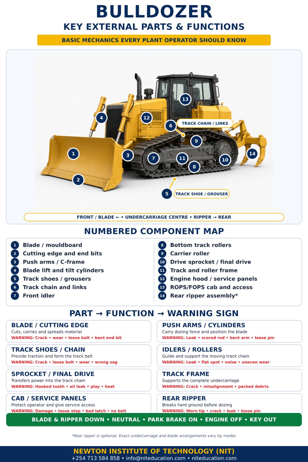
Start at the front
The bulldozer blade and its working parts
The blade is the part most people recognise first. It sits across the front of the machine and does much of the visible work: cutting into material, pushing soil, spreading fill, clearing ground and shaping a surface.
A blade is more than one sheet of steel, though. Its face, wear edges, supporting structure and hydraulic cylinders all have different jobs.
The broad curved surface helps control material as the bulldozer moves forward and helps the material roll and move along the blade.
The cutting edge works against the ground. End bits protect the outer blade corners where wear can be heavy.
This heavy structure carries pushing loads from the blade back into the tractor.
Hydraulic cylinders raise, lower and position the blade; some arrangements also provide tilt or angle functions.
These parts take punishment. A rounded cutting edge, badly worn corner, crack or missing fastener can affect how the blade performs. An operator should be able to notice that change without needing to diagnose the repair.
Watch a blade being lifted and you can see the cylinder rods extending or retracting. If a normally smooth movement becomes slow or jerky, the blade begins drifting, or hydraulic oil appears around a cylinder or hose connection, something has changed.
Do not use your hands to search for a suspected pressurised hydraulic leak.
Crawler running gear
The undercarriage: where many beginners get confused
Look below a crawler bulldozer and you will find one of its busiest systems. The undercarriage supports the machine and provides the path along which the tracks move. It includes the track assembly, rollers, front idler, drive sprocket and related components.
Several of these parts sit close together. Once you understand which part supports, which guides and which drives, the layout becomes much easier to follow.
Track shoes and grousers
The broad steel plates touching the ground spread the machine’s weight. Raised grousers help the track grip the ground.
Track chain, links, pins and bushings
Track links make up the chain. Pins and bushings connect the links and allow the chain to flex around the undercarriage.
Track rollers
Rollers beneath the track frame carry much of the machine’s weight and guide the lower track run. They do not drive the track.
Carrier rollers
Where fitted, carrier rollers support and guide the returning chain across the top of the undercarriage.
Front idler
- Guides the track as the chain changes direction around the front.
- Often works with the track-adjusting and recoil arrangement.
- Its main job is guidance rather than drive.
Drive sprocket
- Uses teeth to engage the track chain.
- Pulls the chain around the undercarriage as the drivetrain turns it.
- The track shoes then react against the ground.
If you are unsure whether you are looking at the idler or the sprocket, look for the component that engages the track with obvious drive teeth. That is the sprocket. The idler’s job is guidance rather than drive.
Track adjuster and recoil arrangement
A crawler track needs the correct relationship between tension and movement. The track adjuster helps maintain that relationship. Many designs also incorporate a recoil arrangement that allows the idler assembly to respond to shock loads or material affecting the track.
An operator should recognise when a track looks unusually loose or behaves differently from normal. Actual measurements and adjustment procedures are machine-specific and should follow the correct technical instructions rather than guesswork.
Final drive
The sprocket still needs enough torque to move a heavy crawler. That is where the final drive comes in. It sits near the end of the powertrain and provides the high-torque output required by the track-drive system.
Engine → transmission/drivetrain → final drive → sprocket → tracks
Exact drivetrain designs differ between machines, but this simplified sequence helps a trainee understand how power eventually reaches the ground. The final drive is not the sprocket, and the sprocket is not the track. Each one performs a separate part of the job.
Structure and power
Main frame, engine and drivetrain
The blade, engine and undercarriage need a strong structure tying the machine together. The main frame provides that foundation. It supports major components and carries the pushing, twisting and travelling loads created during work.
Operators naturally pay more attention to the tracks or blade, but structural damage around a frame or mounting point should never be dismissed simply because the machine can still move.
Engine
The engine is the bulldozer’s primary power source. Familiarity with its normal starting sound, idle, exhaust appearance and response under load helps an operator notice a change.
Cooling system
A radiator or cooling package, fan and coolant circuit carry away heat produced while the machine works under load.
Air intake and air cleaner
The air cleaner traps contaminants before intake air reaches the engine. Damaged intake parts or a restriction warning should not be ignored.
Transmission and drivetrain
Different machines use different drivetrain technologies. At operator level, the key relationship is that the drivetrain transfers engine power towards the final drives and track-drive system.
Open the engine compartment and there is suddenly much more to look at. Do not try to memorise every hose and fitting on the first day. Start with the main systems.
After spending time around the same machine, operators begin to recognise its normal behaviour. A new vibration, different exhaust smoke, loss of power or abnormal temperature becomes much easier to notice when you already know what normal feels like.
Dust and debris can interfere with airflow through a cooling package. Never casually open a hot pressurised cooling system.
Attachment control
The hydraulic system
Travel power gets the bulldozer to the work. Hydraulics control what the working attachments do when it gets there.
Pressurised hydraulic fluid operates cylinders controlling the blade and, where fitted, the rear ripper.
Part of the hydraulic system that supplies hydraulic flow.
The reservoir stores hydraulic fluid while filters help protect the system.
Valves, hoses and rigid lines direct hydraulic fluid through the system.
Cylinders turn hydraulic pressure into controlled blade or ripper movement.
A trainee does not need to trace every hose around the machine. Start with behaviour. If a blade that normally responds smoothly begins moving slowly, jerking or behaving differently, that change is useful information. The same applies to new hydraulic noise or visible leakage.
Recognise what has changed and report it clearly rather than continuing until the problem becomes much larger.
At the rear
The ripper
Walk around to the back of a ripper-equipped bulldozer and the working tool looks completely different from the blade. It has a completely different job.
The ripper uses one or more heavy shanks to penetrate and loosen hard or compacted ground before the material is pushed or moved. Not every bulldozer has one.
Ripper shank
- The heavy member extending towards the ground.
- Penetrates hard or compacted material.
Ripper tip
- Sits at the working end of the shank.
- Takes direct contact with the material and therefore becomes a wear point.
The blade moves and shapes material. The ripper loosens difficult ground.
Operator compartment
Inside the bulldozer cab
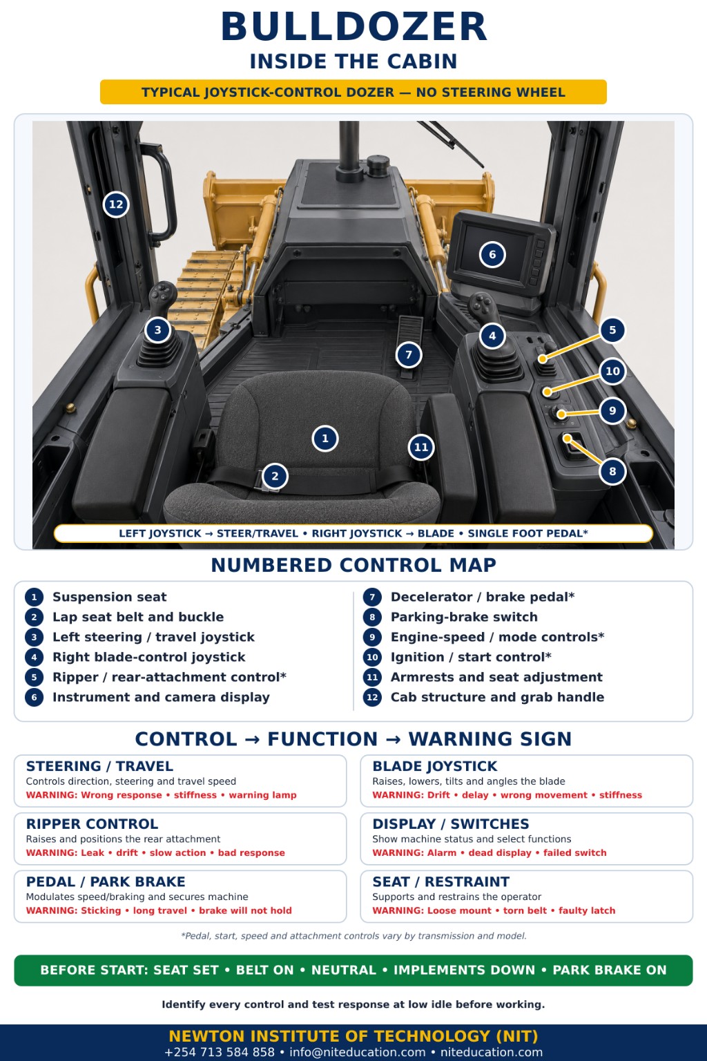
Sit in the operator’s seat and the machine looks different again. Instead of rollers, steel frames and track components, you are looking at levers or joysticks, pedals, switches and a monitor or instrument panel.
Exact arrangements differ between bulldozers, but the main control groups may include:
- travel and steering;
- forward and reverse selection;
- engine-speed control;
- blade controls;
- ripper controls where fitted;
- braking or deceleration controls;
- machine-monitoring displays; and
- lights and other electrical controls.
The purpose of this section is not to teach bulldozer operation from a picture. It is to help a trainee recognise what each control group is responsible for before the machine begins moving.
The operator area may incorporate a rollover protective structure (ROPS) as part of the machine’s protective system. It is more than an ordinary cab roof. The operator restraint or seat belt works as part of that protection. Detailed worksite safety belongs in NIT’s separate Plant Operator Safety Rules guide; here, the important point is knowing what the components are and why they are present.
Service points
Inside the engine and service compartment
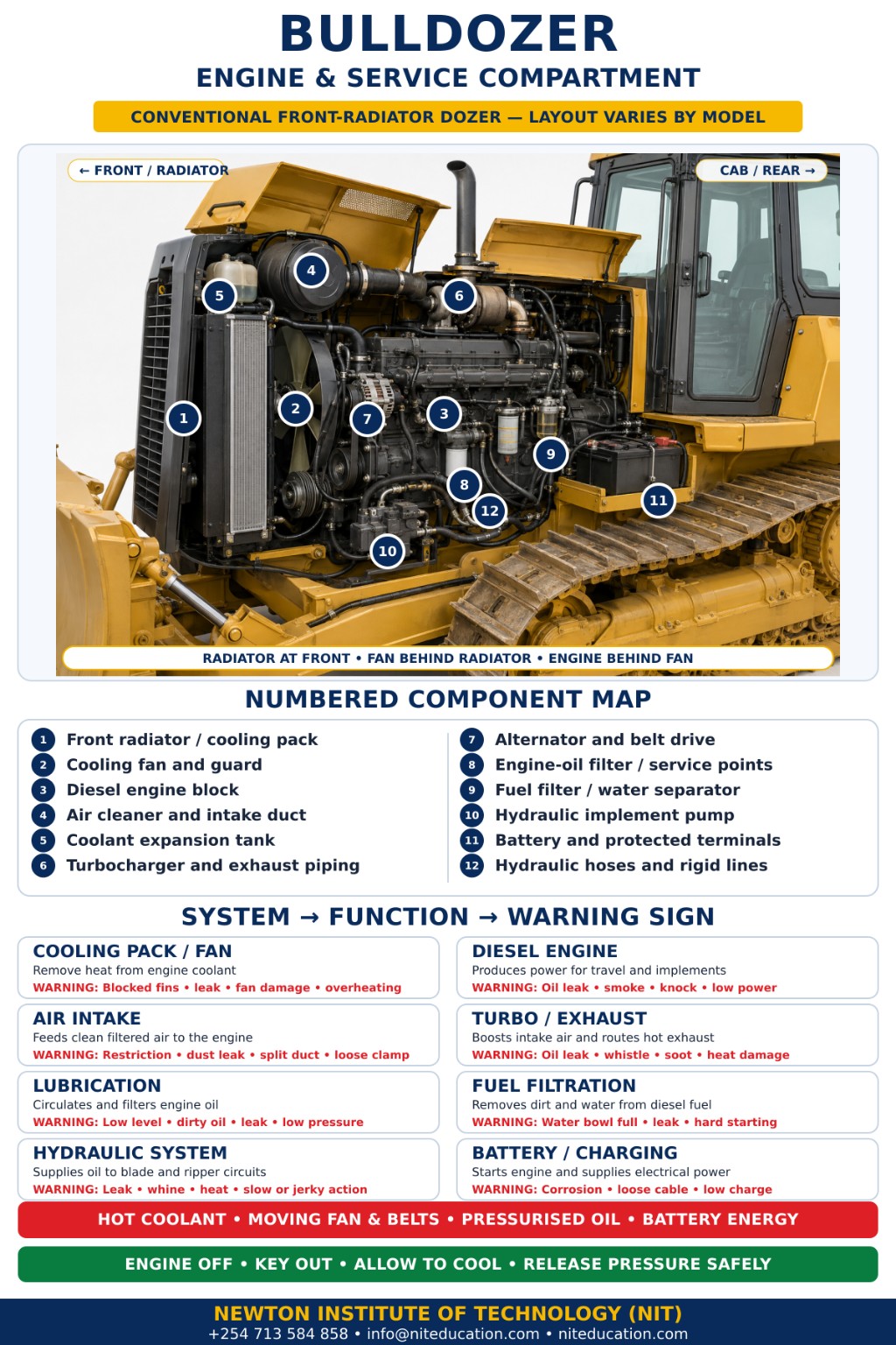
When trainees first open an engine compartment, there is a temptation to identify everything at once. There is no need.
Start with the components and service points you are expected to recognise during normal machine familiarisation.
| Component | Why it matters | |
|---|---|---|
| Engine | Main source of machine power | |
| Engine-oil checking point | Used during the correct routine oil-level procedure | |
| Air cleaner | Helps protect the engine from airborne dirt | |
| Radiator / cooling package | Removes unwanted heat | |
| Coolant checking point | Allows coolant condition or level to be checked correctly | |
| Fuel filter / water separator | Helps provide clean fuel | |
| Hydraulic reservoir | Stores hydraulic fluid | |
| Batteries | Supply starting and electrical-system power | |
| Belts and hoses | Carry drive or fluids between components | |
| Filters | Help protect the systems in which they are installed | |
Service-point locations differ from one machine to another. Learn the actual bulldozer you are using rather than memorising one engine-bay picture and expecting every machine to match it.
Follow the working chain
How all these parts work together
A long list of component names becomes easier to remember when you follow what happens during a push.
The engine produces the power.
Power moves through the drivetrain towards the final drives.
The final drives turn the sprockets, which pull the tracks around the undercarriage.
Track shoes provide traction while the hydraulic system positions the working attachment.
On a conventional crawler arrangement, the track shoes react against the ground and give the machine traction. At the same time, the hydraulic system positions the blade where the operator needs it. Now the blade can work against the material.
That is why the machine should be thought of as a group of connected systems rather than a collection of separate parts.
Common beginner confusion
Bulldozer parts beginners often mix up
Sprocket and idler
The sprocket drives the track. The idler guides it.
Track shoe and track chain
The shoe touches the ground. The chain is the linked structure carrying those shoes around the undercarriage.
Track roller and carrier roller
Track rollers support the lower run. A carrier roller, where fitted, supports the returning track above.
Final drive and sprocket
The final drive provides high-torque rotation. The sprocket uses that rotation to engage the track chain.
Blade and cutting edge
The blade is the complete front working structure. The cutting edge is the wear component along its lower working edge.
Blade and ripper
The blade cuts, pushes, spreads and shapes material. The ripper loosens hard or compacted ground.
These distinctions may sound small during theory lessons. They become much more important when an operator needs to explain exactly where an unusual sound, movement or visible problem is coming from.
Operator observation
Why parts knowledge makes inspections more useful
A checklist becomes easier to use when you understand what it is asking you to look at.
- If the checklist says to inspect the sprocket, you know where it is and what it does.
- If it mentions rollers, you do not confuse them with the idler.
- If you see hydraulic oil around a blade cylinder, you know which system is involved even if you are not the person who will repair it.
That is where basic mechanics becomes useful at operator level.
For the complete inspection sequence, use NIT’s Plant Operator Pre-Start Inspection Checklist.
Recognise the change
- visible leak
- unusual wear
- new noise
- damaged component
- poor track behaviour
- attachment responding differently from normal
Knowing a part is not the same as repairing it
- Recognise the change.
- Describe it clearly.
- Follow the proper reporting or maintenance procedure.
Detailed servicing and preventive maintenance belong in NIT’s Heavy Machinery Maintenance guide.
Practical operator perspective
Why every bulldozer operator should know basic mechanics
Spend enough time around one machine and you start noticing small things. One side of the undercarriage sounds different. The blade takes a little longer to lift. A track does not sit the way you remember it. There is dampness around a hose connection that was dry before.
None of those observations require you to strip the machine apart. They require you to know what normal looks and feels like.
“The more familiar you are with your machine, the easier it becomes to notice when something is not quite right.”
Machine-component identification · practical operator familiarisation · operator observation vs technical repair
Quick reference
Frequently asked questions
What are the main parts of a bulldozer?
The main parts of a crawler bulldozer include the blade, push arms, hydraulic cylinders, track shoes, track chain, rollers, front idler, drive sprocket, final drives, engine, transmission, hydraulic system, operator cab and a rear ripper where fitted.
What are the main parts of a bulldozer undercarriage?
The undercarriage includes track shoes, track links or chain, pins and bushings, track rollers, carrier rollers where fitted, the front idler, drive sprocket and track-adjusting components.
What part drives the bulldozer tracks?
The drive sprocket engages and moves the track chain. Power reaches the sprocket through the machine’s drivetrain and final-drive system.
What is the difference between a sprocket and an idler?
The sprocket is driven and moves the track chain. The idler mainly guides the track around the undercarriage.
What does a bulldozer final drive do?
The final drive provides high-torque output near the end of the drivetrain so the drive sprocket can move the track.
What does a bulldozer blade do?
The blade cuts, pushes, spreads, clears and levels material depending on the job and blade arrangement.
What does a bulldozer ripper do?
A rear ripper uses one or more shanks to penetrate and loosen hard or compacted ground. Not every bulldozer is fitted with one.
What does the hydraulic system do on a bulldozer?
The hydraulic system powers controlled attachment movement, including blade functions and ripper movement where a ripper is fitted.
Are all bulldozers built the same way?
No. The major mechanical principles are similar, but crawler and wheeled machines use different running gear, and blade arrangements, powertrains, controls and service-point locations can vary between bulldozers.
Final takeaway
Learn the machine before you move it
A bulldozer becomes much easier to understand once you stop seeing it as one huge piece of equipment. The engine produces the power. The drivetrain carries that power towards the tracks. The final drives turn the sprockets. The sprockets move the track chains. The track shoes put that effort into the ground. Hydraulics position the blade or ripper. And the operator brings those systems together to do the work.
In Kenya’s Category G machine classification, the bulldozer is identified as G3. For course requirements and practical training, see NIT’s Bulldozer Operator Training in Kenya guide. Licensing questions belong in the separate NTSA Category G Plant Operator Licence guide.
At Newton Institute of Technology, machine familiarisation is part of learning plant operation practically: know the part, understand its job and recognise when its behaviour changes.
Prepared by: Newton Institute of Technology Editorial Team · Institutional / Technical review: Engineer Simon Barongo · Last reviewed: September 2026