

Know Your Machine G7 Backhoe Loader
Backhoe Loader Parts
& Functions
Load · Dig · Stabilise · Control
Basic mechanics for plant operators: identify the main backhoe-loader parts, understand what they do and learn what normal machine movement, sound and response should feel like.
What are the main parts of a backhoe loader?
The main parts of a backhoe loader are the front loader, tractor or power unit, rear backhoe and hydraulic system. Important components include the loader bucket and arms, main frame, engine, transmission, cab, boom, dipper, rear bucket, stabilizers, swing system, hydraulic pump, hoses, cylinders, pins and bushings.
Machine anatomy
Backhoe loader parts and functions at a glance
A backhoe loader is easy to recognise from a distance: a large loader bucket at the front, a digging arm at the rear and a cab between the two. Once you start learning the machine properly, you realise several mechanical and hydraulic systems are working together every time it drives, raises a bucket, swings the backhoe or settles onto its stabilizers.
People often use the word backhoe to mean the whole machine. Technically, the backhoe is the rear digging assembly. The complete machine—with a front loader at one end and a backhoe at the other—is a backhoe loader.
| Component | Where it is | Main function |
|---|---|---|
| Front loader bucket | Front | Scoops, carries, backfills and levels material |
| Loader arms | Front | Raise and support the front bucket |
| Lift cylinders | Front loader assembly | Raise and lower the loader arms |
| Tilt cylinders & linkage | Around front bucket | Curl and dump the bucket |
| Main frame / chassis | Centre | Supports and connects the major machine systems |
| Engine | Tractor unit | Produces power |
| Transmission | Tractor unit | Transfers engine power into usable movement |
| Axles & drivetrain | Beneath tractor unit | Transfer drive to the wheels |
| Operator’s cab | Centre | Houses the operator, controls and instruments |
| Hydraulic pump | Power unit | Produces hydraulic oil flow |
| Boom | Rear backhoe | Raises and lowers the digging assembly |
| Dipper / stick | Between boom and bucket | Changes digging reach |
| Rear bucket | End of dipper | Cuts and collects material |
| Swing tower / king post | Rear mounting structure | Allows controlled side-to-side movement |
| Stabilizers / outriggers | Rear sides | Help steady the machine during digging |
| Pins & bushings | Pivot joints | Allow controlled movement between components |
The precise layout varies by machine. Learn the actual machine in front of you and follow its operator manual for machine-specific procedures.
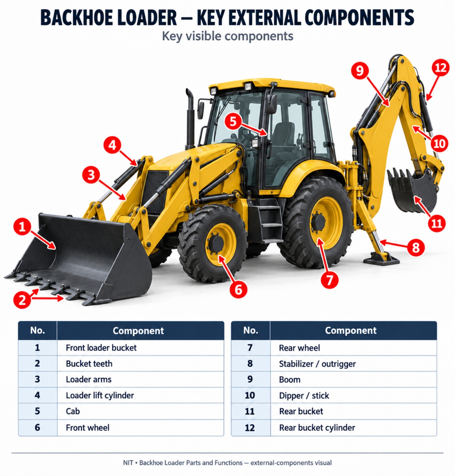
Visual: Backhoe loader key external components. Supplied infographic used unchanged.
Start with four areas
The easiest way to understand a backhoe loader
Trying to memorise every part at once can make the machine seem more complicated than it really is. Start with four connected working areas.
The loading end. Loader arms and the front bucket scoop, lift, carry, backfill and level material.
The centre. It contains the frame, engine, transmission, drivetrain, steering, brakes, axles, wheels and cab.
The digging end. Its three most recognisable working parts are the boom, dipper and bucket.
The working force. Hydraulics move the loader arms, buckets, boom, dipper, stabilizers and swing mechanism.
Front working end
Front loader parts and functions
The front of a backhoe loader works much like a wheel loader. It handles loose material, loads vehicles, backfills excavations and can carry out light levelling work.
Front loader bucket
The main material-handling attachment. It scoops, lifts, carries, loads, backfills and pushes loose material. A bucket takes punishment, so cutting edges and teeth are expected to wear.
Loader arms & lift cylinders
The arms carry the bucket and load; hydraulic cylinders provide the lifting force. A new knock, extra play, uneven movement or settling is worth reporting.
Tilt cylinders & linkage
Tilt cylinders curl the bucket back to retain material and rotate it forward to dump. The linkage converts straight cylinder movement into useful bucket rotation.
Cutting edge & teeth
These are wear components. The cutting edge scrapes or enters material; teeth, where fitted, concentrate force to improve penetration.
Structure, power and travel
Main frame, tractor and power unit
Underneath the obvious moving components is the machine’s structural backbone. The main frame or chassis supports the tractor unit and ties the front loader and rear backhoe into one machine.
Engine, transmission & drivetrain
- The engine produces power and drives the hydraulic pump.
- The transmission turns engine power into controlled machine movement.
- Drive shafts, differentials, axles and final-drive components carry power towards the wheels.
- A new vibration, noise, delay or harsh engagement can be an early clue that something has changed.
Axles, tyres, steering & brakes
- Axles support weight and transmit drive while handling travel and steering forces.
- Tyres provide support, traction and mobility.
- The steering system converts steering-wheel movement into wheel direction.
- Service brakes stop a moving machine; the parking brake holds a stationary one.
Rear working end
Rear backhoe parts and functions
The rear digging attachment gives the machine its name. The three main working parts are easy to remember: Boom → dipper → bucket.
The first large section closest to the machine. It raises and lowers the digging assembly and carries substantial excavation forces.
Sits between boom and rear bucket. Its movement changes the bucket’s reach.
The bucket cuts and collects material. Its linkage converts cylinder movement into bucket curl.
Pivot joints let the boom, dipper and bucket move in a controlled way while carrying heavy loads.
On a worn joint, you may hear a clack as the bucket changes direction before you can clearly see anything wrong. That is the kind of small change operators learn to recognise with experience.
Rear mounting & support
Swing tower, king post and stabilizers
Swing tower / king post
- The rear digging assembly must be strongly connected while still moving side to side.
- Terms may include swing tower, king post, centre pivot or side-shift carriage.
- Centre-pivot machines swing around a central rear mounting point.
- Side-shift arrangements can move the digging assembly laterally across the rear structure.
Stabilizers / outriggers
- Two rear stabilizers help steady the machine during excavation.
- Hydraulic cylinders lower the legs and pads transfer load to the supporting ground.
- They help create a firmer working base but do not make unsuitable ground safe.
- Ground conditions still have to be assessed correctly.
For wider worksite and positioning guidance, see NIT’s Plant Operator Safety Rules in Kenya.
The working force
The hydraulic system
Most major working movements on a backhoe loader are hydraulic: loader lift, bucket tilt, boom, dipper, rear-bucket curl, swing and stabilizer movement.
Hydraulic pump & control valves
The pump creates oil flow. Control valves direct that flow to whichever circuit the operator commands.
Reservoir & filter
The reservoir stores hydraulic oil. The filter removes contamination from the circulating oil and helps protect precision components.
Hoses & pipes
Hoses carry oil between components, especially where attachments move. Never use a bare hand to search for a suspected high-pressure hydraulic leak.
Hydraulic cylinders
Cylinders turn pressurised oil into straight-line movement for loader lift, bucket tilt, boom, dipper, stabilizers and other functions.
For the complete before-work routine, use NIT’s Plant Operator Pre-Start Inspection Checklist.
Small parts, big loads
Pins and bushings
A pin forms the pivot shaft around which connected parts move. A bushing provides a bearing or wear surface around many of those pins. Almost every major moving attachment depends on them.
- Loader-arm and front-bucket linkage joints
- Boom, dipper and rear-bucket joints
- Stabilizer and other articulated connections
- Watch for knocking when movement changes direction
- Notice visible sideways play or less precise control
- Report the symptom; qualified maintenance personnel diagnose and repair
Operator control centre
Inside the backhoe loader cab
The cab is the machine’s control centre. Exact layouts differ, but the main functions are broadly similar.
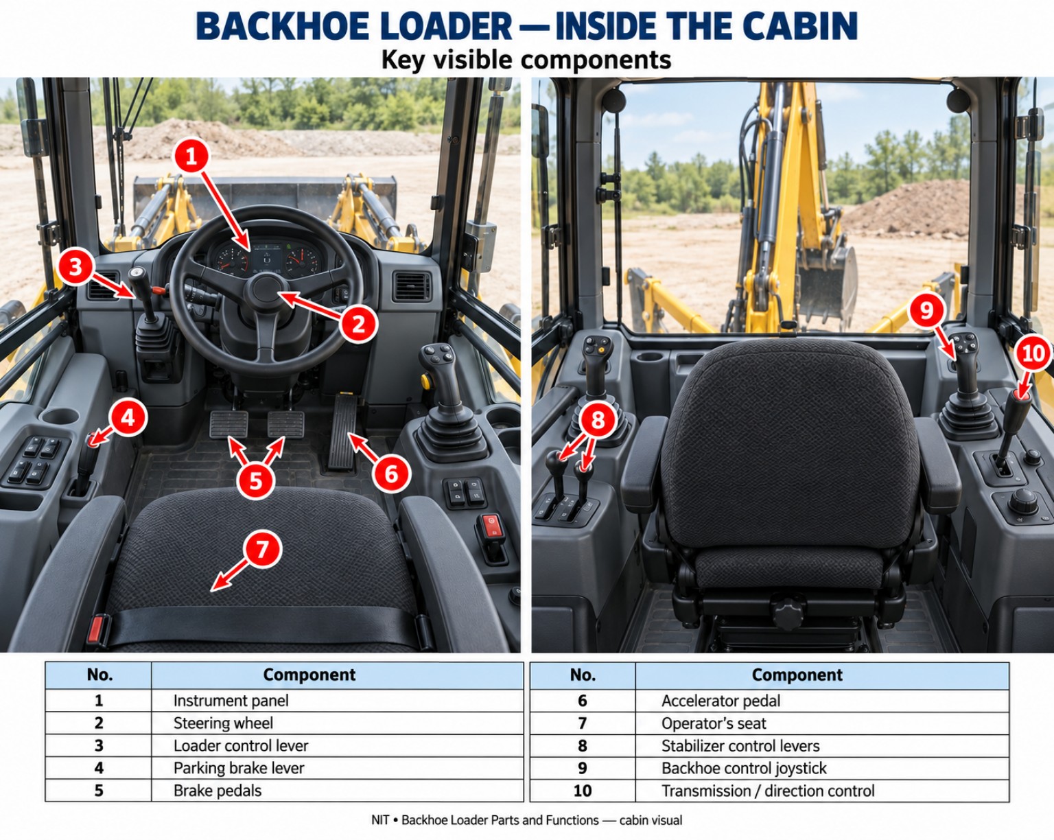
Visual: Backhoe loader cabin components. Supplied infographic used unchanged.
Seat, seat belt & protection
The seat commonly faces forward for travel and loader work and rearward for backhoe work. The seat belt works with the protective structure. ROPS and FOPS protection depends on the certified structure fitted.
Steering & loader controls
The steering wheel controls travel direction. Loader controls raise, lower, curl and dump the front attachment.
Backhoe controls
Rear controls operate boom, dipper, bucket and swing functions. Control patterns can differ between machines, so never assume an unfamiliar machine is identical.
Instrument panel
The dashboard communicates fuel, temperature, engine speed, operating hours, transmission information and warning indicators. A warning light that appears today but was not there yesterday is information.
Service-area orientation
Inside the engine compartment
Engine-compartment layouts vary. Learn the actual machine in front of you rather than assuming every backhoe loader places components in the same position.
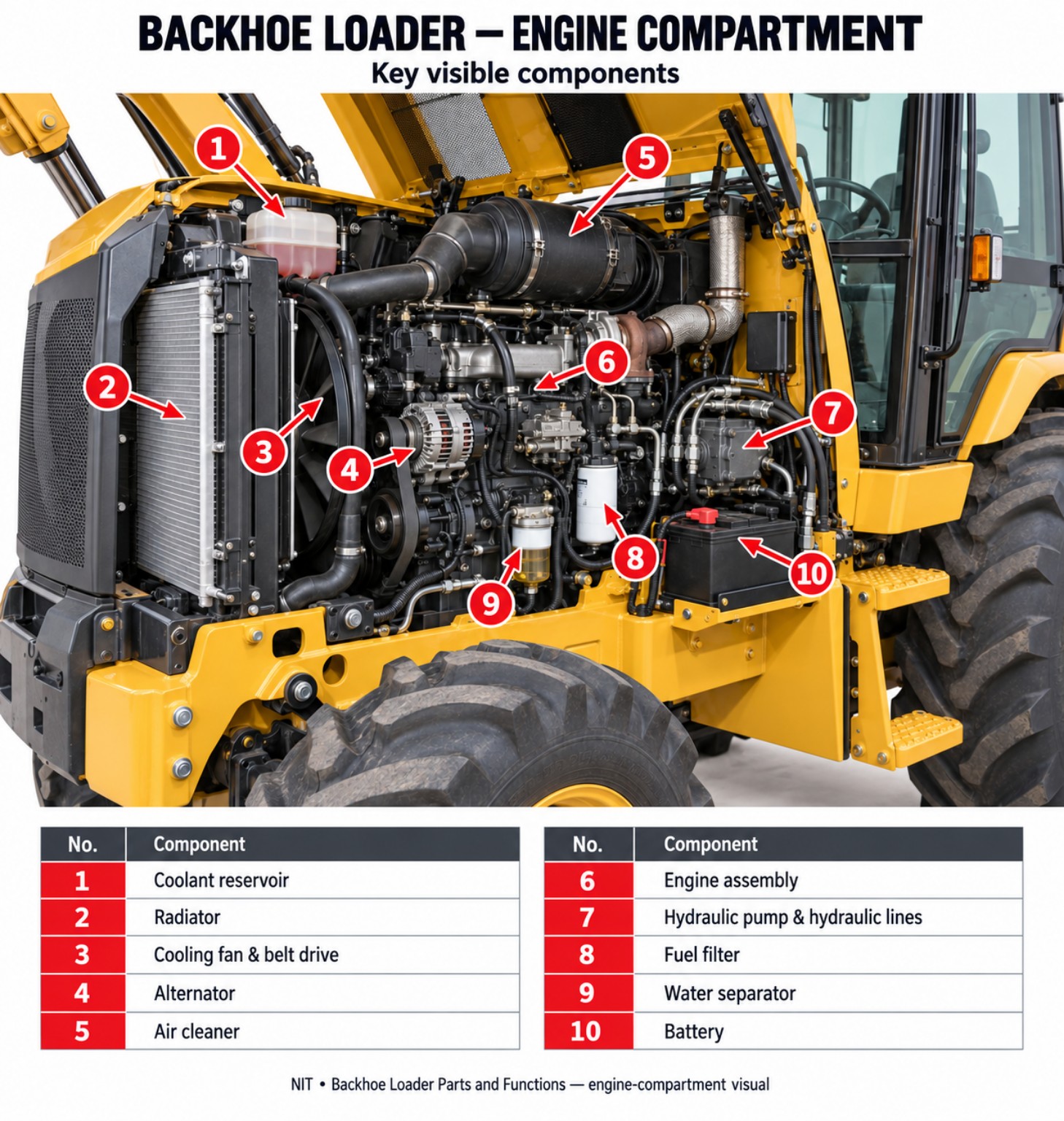
Visual: Backhoe loader engine-compartment components. Supplied infographic used unchanged.
Engine & engine oil
The engine is the main power source. Engine oil lubricates internal moving parts. Operators should know the correct machine-specific checking point and procedure.
Cooling system
The radiator, coolant reservoir, hoses, fan and related components remove excess heat. A machine running hotter than usual is telling you something has changed.
Air & fuel service components
The air-cleaning system keeps dust out of the engine. Fuel filters and water separators help protect sensitive fuel-system parts from contamination.
Battery & belts
The battery supplies starting and electrical power. Some engine accessories are belt driven. An operator should know what normal visible condition looks like on the machine used.
Clear machine language
Don’t confuse these backhoe loader parts
| Components | Difference | Memory cue |
|---|---|---|
| Boom vs dipper | Boom is closest to the machine; dipper connects boom to bucket. | Boom → dipper → bucket |
| Dipper vs stick | Two common names for the same component. | Same part |
| Front vs rear bucket | Front bucket mainly loads and carries; rear bucket mainly excavates. | Front = load, rear = dig |
| Loader arms vs boom | Loader arms belong to the front loader; boom belongs to the rear backhoe. | Different working ends |
| Hose vs cylinder | A hose carries hydraulic oil; a cylinder converts pressure into movement. | Carry vs move |
| Reservoir vs filter | The reservoir stores oil; the filter removes contamination. | Store vs clean |
| Pin vs bushing | The pin forms the pivot shaft; the bushing provides the wear surface. | Pivot vs wear surface |
| Service vs parking brake | Service brake stops the machine; parking brake holds it. | Stop vs hold |
Knowing the names makes fault reporting clearer. “There is play at the dipper-to-bucket joint” tells a technician far more than “something at the back is loose.”
See the systems working together
How the main parts work together during digging
Engine, transmission, drivetrain, steering and wheels bring the machine into place.
Rear stabilizers are lowered onto suitable ground.
The boom positions the digging assembly vertically.
The dipper moves the bucket closer to or farther from the machine.
The bucket cylinder and linkage rotate the bucket through the material.
The boom and dipper raise the bucket clear.
The swing system moves the rear assembly towards the spoil area.
The bucket rotates and releases the material.
From a distance this can look like one smooth movement. Mechanically, several cylinders, valves, pivot joints and structural parts are sharing the work. This is a mechanical explanation, not an operating lesson.
For practical G7 operation, duration and training requirements, see NIT’s Backhoe Loader Training in Kenya guide.
At the other working end
How the front-loader parts work together
The loader arms provide the lifting structure. Hydraulic cylinders move the arms. Tilt cylinders and linkage control bucket angle. The bucket handles the material.
Behind the attachment, the engine provides power, the drivetrain moves the machine, steering controls direction and brakes control stopping. A backhoe loader is much more than a tractor with two buckets.
Operator awareness
What changes should an operator notice?
Once you know a particular machine well, small changes become easier to spot. These observations do not automatically tell you which component has failed; they tell you that something has changed.
- A new knock at a pivot
- More play at a joint
- Oil appearing around a hose or cylinder
- One hydraulic function becoming slower
- Unusual steering or braking behaviour
- A new vibration or warning indicator
- A stabilizer or attachment that no longer holds as expected
- Operators report symptoms. Qualified maintenance personnel diagnose faults.
Six ideas to remember
A simple way to remember the machine
Front — load. Centre — power, drive and control. Rear — dig.
Hydraulics — move the working attachments. Stabilizers — support the rear during digging. Frame — holds the machine together.
Know your responsibility
Basic mechanics does not mean repairing the machine
A capable operator understands the equipment and also knows where operator responsibility ends. Basic mechanical knowledge helps you identify parts correctly, recognise normal movement, notice changes and communicate defects clearly.
It does not mean opening hydraulic systems, dismantling safety-critical components or attempting repairs for which you are not trained or authorised.
For servicing and preventive maintenance, use NIT’s Heavy Machinery Maintenance in Kenya guide.
Common questions
Frequently asked questions
What are the main parts of a backhoe loader?
The main sections are the front loader, tractor or power unit, rear backhoe and hydraulic system. Important parts include the loader bucket and arms, main frame, engine, transmission, cab, boom, dipper, rear bucket, stabilizers, swing system, hydraulic components, pins and bushings.
Is a backhoe the same as a backhoe loader?
Not exactly. Technically, the backhoe is the rear digging assembly. A backhoe loader is the complete machine with a front loader, tractor unit and rear backhoe.
What are the three main parts of the rear backhoe?
The three main working components are the boom, dipper and bucket. The boom is closest to the machine, the dipper sits between boom and bucket, and the bucket performs the excavation.
What is the difference between the boom and dipper?
The boom is the first large section attached to the machine. The dipper, also called the stick, connects the boom to the bucket and changes digging reach.
What does the main frame do?
The main frame or chassis is the structural backbone of the machine. It supports major systems and carries forces between the front loader, tractor unit and rear backhoe.
What do backhoe stabilizers do?
Stabilizers help steady the rear of the machine during excavation. They provide additional support but do not replace proper assessment of the ground.
What powers the boom, dipper and buckets?
The hydraulic system provides the working force. The engine drives the hydraulic pump, control valves direct the oil and hydraulic cylinders create movement.
What are pins and bushings?
Pins form pivot shafts. Bushings provide bearing or wear surfaces around many of those pins. Together they allow large machine components to pivot in a controlled way.
What is a swing tower or king post?
It is part of the rear mounting structure connecting the digging assembly to the main machine while allowing controlled side-to-side movement. Terminology and design vary between machines.
Is a backhoe loader the same as an excavator?
No. A conventional backhoe loader is a tractor-based machine with a front loader and rear backhoe. An excavator uses a different layout built primarily around excavation.
From the workshop floor
Learn the normal feel of the machine
“Once you know how the machine normally feels, you notice changes much earlier. A new knock, extra play or a slow response is often where the story starts.”
Engineer Simon Barongo
Institutional / Technical review
Learn by seeing, then by doing
Join Newton Institute to learn more
Learning the names of the parts gives you the foundation. Practical training is where the names begin to make sense as you see the loader arms carry a real load, feel the difference between boom and dipper movement and learn how the machine responds.
MachineG7 Backhoe Loader
Learning approachBasic mechanics + practical operation
InstitutionNewton Institute of Technology