

Know Your Machine G5 Motor Grader
Motor Grader Parts
& Functions
Blade · Circle · Wheel lean · Tandem drive
Basic mechanics for plant operators: understand the grader’s working equipment, steering geometry, tandem drive, cab controls, engine systems and the warning signs worth reporting.
Operator-level machine knowledge
Stand beside a motor grader for the first time and the blade area can look complicated. There is the moldboard, a large circle, hydraulic cylinders, the drawbar, linkages and several different ways of moving what appears to be the same blade.
It becomes much easier once you follow one mechanical relationship:
That is the heart of the grader. The engine provides power. Hydraulics position the working equipment. The tandem drive gets that power to the ground. Wheel lean and articulation help position the machine while the blade works.
For a plant operator, basic mechanics is not about stripping an engine or repairing hydraulic components. It starts with something more practical: knowing which part you are looking at, what it is supposed to do and when its behaviour has changed.
What are the main parts of a motor grader?
The major parts include the moldboard, cutting edge, circle, circle drive, drawbar, saddle, blade lift cylinders, side-shift system, blade-pitch mechanism, centershift, front axle, wheel-lean system, articulation joint, tandem drive, engine, transmission, hydraulics, cab controls, scarifier and, where fitted, a rear ripper.
Motor grader key external parts and functions
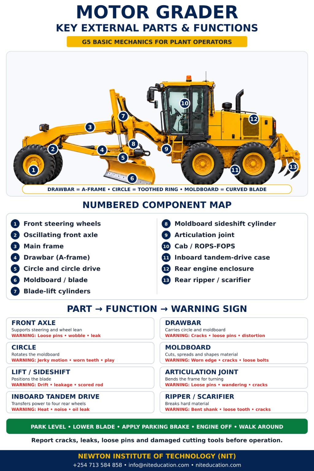
Start with the part that does the grading
The grader’s working equipment
The moldboard is the most obvious working part, but it is only one piece of the system. The drawbar carries the main working assembly. The circle allows the moldboard to rotate. The moldboard controls and carries material. The cutting edge works directly against the ground. Hydraulic cylinders position those parts.
Moldboard or grader blade
The long curved blade beneath the centre of the grader cuts material, spreads gravel or soil, trims high spots, shapes road surfaces, forms shoulders and helps develop drainage profiles.
Its curved face helps material move and roll along the blade. The operator can normally change its height, angle, lateral position, pitch and cross-slope.
Cutting edge and end bits
The replaceable cutting edge is fitted along the bottom of the moldboard and takes much of the direct wear from the surface. Replaceable end pieces may protect the ends of the moldboard.
Uneven wear, cracks or loose fasteners can change how the blade contacts the ground even when the rest of the grader appears normal.
Moldboard toe and heel
Once the moldboard is angled across the machine, the toe is the leading end and the heel is the trailing end.
These are not separate components. The terms help an operator understand blade angle, material flow and where the windrow is leaving the blade.
Circle and circle drive
The large circle above the moldboard allows the blade to rotate. The circle drive produces that movement so the blade can work at different angles across the machine.
New knocking, excessive play, jerky rotation or difficulty holding the selected angle is worth reporting.
Drawbar, saddle and blade-lift cylinders
Drawbar
- Connects the main working equipment to the grader frame.
- Supports the circle and moldboard assembly.
- Carries the forces created while the cutting edge works against the ground.
- Remember it as: the drawbar carries it; the circle turns it.
Saddle and lift system
- The saddle forms part of the support and positioning arrangement around the front-frame area.
- Blade-lift cylinders control moldboard height.
- The two sides can normally be adjusted independently.
- Unequal response, leakage or a blade that will not hold its position shows that something has changed.
Four movements beginners often mix up
Blade angle, pitch, side shift and centershift
The circle rotates the moldboard across the grader.
The moldboard tilts forward or backward, changing its relationship with the material.
The moldboard itself moves laterally left or right.
A larger part of the drawbar-circle-moldboard assembly is repositioned sideways.
From the cab, several controls can look as though they are doing versions of the same job. They are not. Blade lift changes height and cross-slope. Circle rotation changes angle. Pitch tilts the blade. Side shift slides the moldboard. Centershift repositions more of the working assembly.
When you operate a control during familiarisation, look outside and ask: Which part actually moved? That links the control to the mechanics much faster than memorising lever names alone.
Steering geometry before the blade reaches the ground
Front axle and front-wheel lean
Front axle
The front axle carries the front wheels and forms part of the steering and ground-following arrangement. The front wheels travel over the surface before the moldboard reaches it, so their position influences how the grader approaches the section about to be cut.
Tyre condition, wheel fasteners, steering connections and unusual movement around the axle all deserve attention during a walk-around.
Front-wheel lean
Grader front wheels can deliberately tilt sideways. Wheel lean changes the sideways angle of the wheels and helps manage forces acting on the machine while an angled blade pushes material.
It can also assist machine positioning and steering behaviour. It should not be treated as simply another form of steering; it is part of the grader’s working geometry.
Two systems that change how the machine holds the ground
Articulation joint and inboard tandem drive
Articulation
- The front and rear frame sections are connected by an articulation joint.
- Hydraulic cylinders allow the two sections to operate at an angle to one another.
- Articulation changes tracking, turning and blade positioning; it is mechanically different from front-wheel steering.
- The articulation area is a serious crushing and pinch zone. Correct isolation and locking procedures are essential before anyone works near the joint.
Inboard tandem drive
- Most graders use four rear wheels, arranged as two wheels on each side.
- The tandem arrangement transfers drive through the rear wheel groups and helps them follow changes in the ground while maintaining traction.
- Oil around a tandem case, new noise, unusual heat or unexpected movement is worth reporting.
- The tandem case is inboard of the rear wheels; do not confuse the visible outer wheel pair with the drive case itself.
Power first, precision through hydraulics
Engine, drivetrain and hydraulic system
Engine and drivetrain
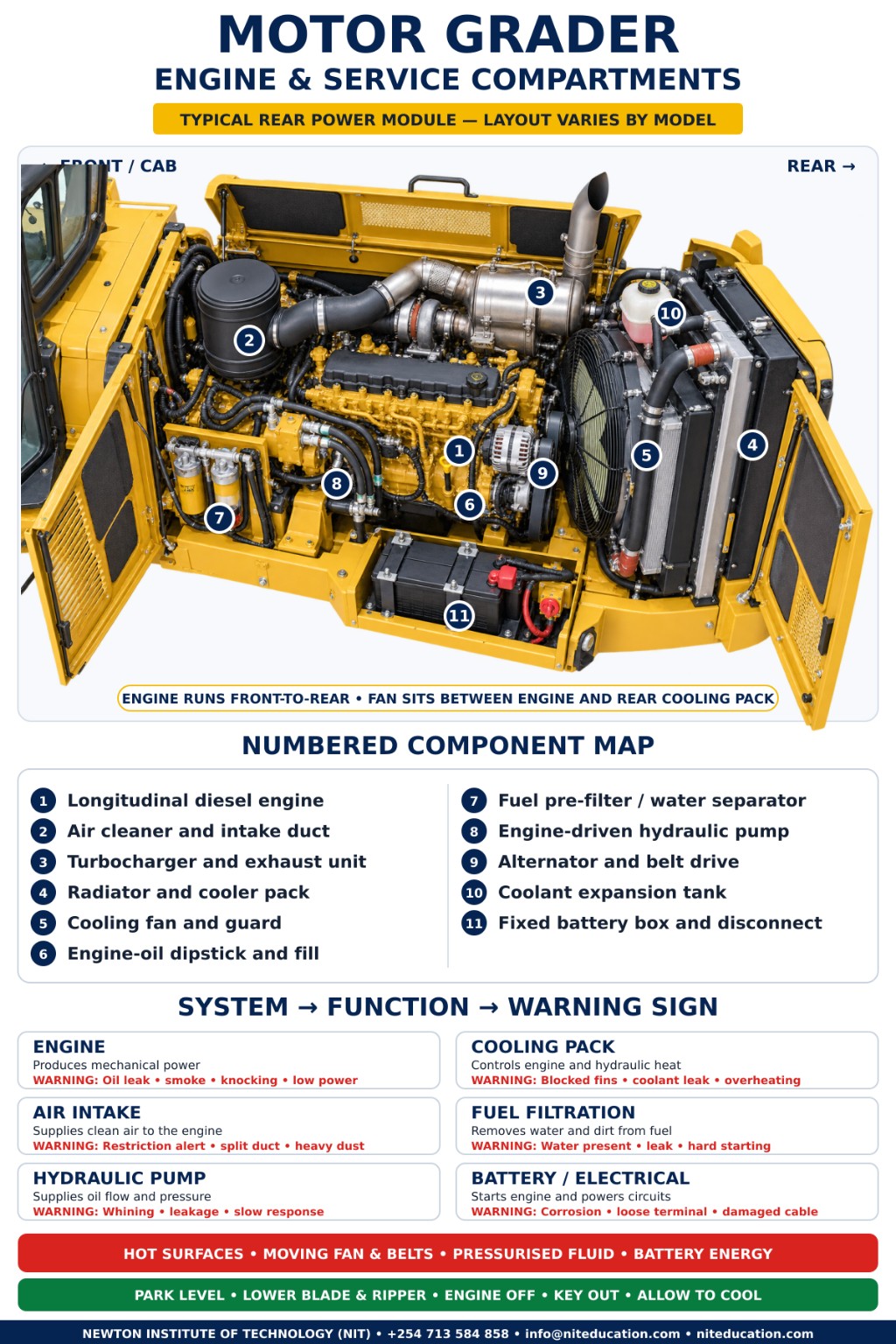
The engine normally sits toward the rear of the grader. It supplies power for machine travel and hydraulic systems. The transmission and drivetrain transfer usable power toward the driving wheels.
At operator level, the key skill is knowing normal behaviour. Unexpected smoke, vibration, overheating, power loss, delayed drive engagement or a new warning indication means something has changed.
Hydraulic system
Hydraulic power may control blade lift, circle position, side shift, pitch, centershift, wheel lean, articulation, scarifier movement and rear attachments.
Visible leakage, damaged hoses, cylinders that drift or controls that suddenly become slow or jerky should not simply be corrected repeatedly from the cab. Never use your hand to search for a suspected high-pressure hydraulic leak.
Scarifier
A scarifier uses several teeth or shanks to loosen a hard or compacted surface before the moldboard works it.
A useful sequence is loosen → grade → shape. Teeth and retaining components work close to the ground, so they need regular visual attention.
Rear ripper
Some graders are equipped with a rear ripper whose heavier shanks can penetrate harder material. A ripper and a scarifier do related jobs, but they are not automatically the same attachment.
Identify what is fitted to the grader in front of you rather than assuming every machine has the same configuration.
The controls make more sense once you know what must move
Inside the motor grader cab
Motor grader control layouts are not universal. Some machines use conventional steering-wheel and lever layouts, while others use joysticks or electronically controlled systems. Before operating an unfamiliar grader, locate each control and understand the movement it produces.
Inside the operator cabin
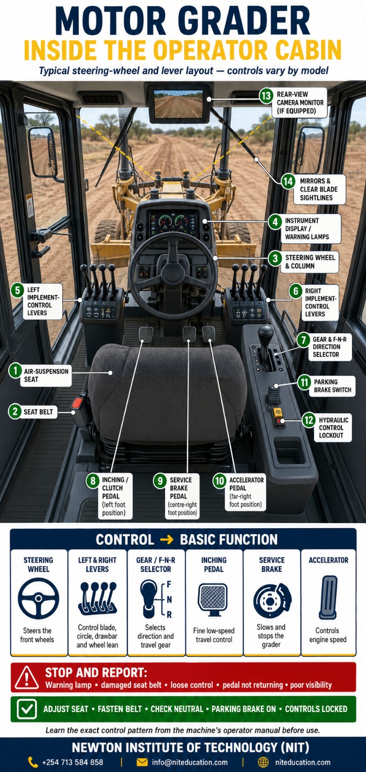
| Control group | Typical function | Operator check |
|---|---|---|
| Steering & direction | Steering wheel or steering controls; forward-neutral-reverse and gear selection. | Know the selected direction and verify the control pattern before travel. |
| Blade controls | Left and right blade lift, circle rotation, side shift and pitch. | Confirm which component moves before trying to coordinate several functions. |
| Geometry controls | Centershift, wheel lean and articulation. | Watch the machine outside the cab so you can connect the control to the actual movement. |
| Travel pedals | Inching/clutch where fitted, service brake and accelerator. | Pedals should return normally and the area around them should be clear. |
| Safety & information | Seat belt, parking brake, hydraulic lockout, warning lamps, display and mirrors/camera where fitted. | Do not ignore a warning indication or poor visibility simply because the grader will still move. |
Look for condition, not a workshop diagnosis
Inside the engine and service compartment
Opening the service panels exposes a different part of the grader from the blade mechanism underneath it. Depending on the machine, the operator may see the engine, cooling package, air intake, filters, batteries, hydraulic components, hoses and normal service check points.
Motor grader engine and service compartments
Part → function → warning sign
Motor grader parts, functions and warning signs
| Part | Main job | A change worth noticing |
|---|---|---|
| Moldboard | Cuts, carries and shapes material. | Damage, looseness or unusual vibration. |
| Cutting edge | Works directly against the surface. | Uneven wear, cracks or loose fasteners. |
| Circle | Rotates the moldboard. | Knocking, excessive play or jerky rotation. |
| Drawbar | Carries and connects the working assembly. | Cracking, looseness or abnormal movement. |
| Blade lift cylinders | Control blade height and cross-slope. | Leakage, drift or unequal response. |
| Blade side shift | Slides the moldboard sideways. | Restricted or uneven movement. |
| Blade pitch | Changes moldboard tilt. | Failure to hold the selected position. |
| Centershift | Moves the larger working assembly sideways. | Jerky movement or leakage. |
| Wheel lean | Tilts the front wheels. | Uneven movement or failure to hold position. |
| Articulation | Angles the front and rear frame sections. | Knocking, looseness or leaking cylinders. |
| Inboard tandem drive | Transfers drive through the rear wheel groups. | Oil leakage, noise or overheating. |
| Hydraulic system | Powers implement movement. | Leakage, drifting or slow response. |
| Scarifier | Loosens compacted material. | Broken or severely worn teeth. |
| Ripper | Breaks harder material. | Damaged shanks or mounting parts. |
Keep the check short and purposeful
A short pre-start grader check
A walk-around is most useful when the operator is looking for change, not simply completing a ritual.
- Look underneath and around the grader for a fresh leak or loose material.
- Check tyres, wheels and the visible front-axle and steering area.
- Look over the moldboard, cutting edge, drawbar, circle and lift cylinders.
- Inspect visible hydraulic hoses, cylinder rods and connections.
- Pay attention to the articulation area and both tandem-drive cases.
- In the cab, check visibility, the seat belt, control condition and warning indications before work.
Detailed servicing schedules and maintenance procedures belong in the dedicated heavy-machinery maintenance material rather than this parts-and-functions guide.
For a new trainee
Five grader parts to understand first
See how the blade contacts and carries material.
Watch how the blade rotates across the machine.
Trace how the working assembly connects back to the frame.
Watch how the front wheels and frame geometry change machine position.
Once those ideas make sense, the cylinders and linkages stop looking like unrelated parts. You begin to see one connected machine.
The practical reason operators learn mechanics
Basic mechanics is really about recognising change
After spending time on the same machine, an operator begins to know its normal behaviour. You know how quickly the blade responds, how the circle sounds, how articulation feels and how the grader reacts when the cutting edge begins working against material.
Many faults first appear as something small: a new sound, slower movement, a blade that drifts, a fresh leak or a control that suddenly needs constant correction. Recognising that difference early is one of the practical reasons plant operators learn basic mechanics.
From practical training
Know what the control is actually doing
“When a trainee understands what each grader part is doing, operating the machine becomes much easier. You stop just moving controls and start knowing why the blade, wheel lean and articulation are reacting the way they are.”
G5 motor grader · operator-level basic mechanicsQuick revision
Frequently asked questions
What is the main working part of a motor grader?
The moldboard, commonly called the grader blade, is the main working tool. It cuts, moves, spreads and shapes material.
What does the circle do?
The circle rotates the moldboard and allows the operator to change its working angle.
What does the drawbar do?
The drawbar carries and connects the circle and moldboard assembly to the grader frame.
What is the cutting edge?
It is the replaceable lower section of the moldboard that works directly against the material being graded.
What is the saddle on a motor grader?
The saddle forms part of the working-equipment support and positioning arrangement and provides mounting positions associated with blade control.
What is the difference between blade angle and blade pitch?
Blade angle describes rotation across the grader. Blade pitch describes the forward or backward tilt of the moldboard.
What is blade side shift?
Blade side shift moves the moldboard itself laterally.
What is centershift?
Centershift moves a larger part of the drawbar-circle-moldboard assembly sideways relative to the grader.
Why do grader front wheels lean?
Wheel lean helps manage the machine’s working geometry and forces created while grading.
What is articulation?
Articulation allows the grader’s front and rear frame sections to operate at an angle to one another.
What is a tandem drive?
It is the rear-wheel drive arrangement that transfers power through the rear wheel groups while allowing them to follow changes in the ground.
Is a scarifier the same as a ripper?
No. Both loosen material, but their construction, location and working capacity may differ.
Do all motor graders have the same controls?
No. Their main functions are similar, but control layout, type and direction can differ between machines.
The simplest way to remember the machine
Drawbar → circle → moldboard → cutting edge
The drawbar carries the assembly. The circle turns the blade. The moldboard controls the material. The cutting edge works against the ground. Wheel lean, articulation, blade lift, pitch, side shift and centershift then give the grader the positioning range needed for precise work.
For a plant operator, the purpose of basic mechanics is straightforward: know the important parts, understand what they are supposed to do and recognise when the grader is no longer behaving normally.
Continue the plant-operator learning path
Related NIT guides
Plant Operator Course Syllabus in Kenya
Plant Operator Training Materials in Kenya
Heavy Machinery Maintenance in Kenya
NTSA Category G Plant Operator Licence Guide
Editorial scope: Operator-level familiarisation with motor grader parts, functions and warning signs. Use the operator manual for the specific grader and follow site procedures for operation, isolation and maintenance.
Turn machine knowledge into practical skill
Join Newton Institute of Technology to learn more
Build practical plant-operator knowledge with guided training that connects machine parts, controls, safety and real operating practice.